By Allan Huang, Analyst
This report serves as a resource to fall back on for readers needing a quick tutorial on the fundamentals of electricity and electrical engineering. Any links to external sources of information have no affiliation to Vivid and are curated for accuracy as much as reasonably possible.
Welcome to our new series at Vivid! Science of Electrification for Investors is our way of showcasing our team’s expertise in breaking down the fundamental technological and economic forces that underlie the energy transition. We hope that as you make your way through this series of short reports, the immense value of electrification becomes ever clearer in your mind. We aim for this series to have the scientific rigor necessary to make informed decisions, but also be understandable for those without formal scientific training.
Currently, we are living through a convergence of multiple, co-dependent lines of innovation and global market trends. Market participants have realized that there exists a triangle of synergy between: energy, semiconductors, and electrical infrastructure. For the first time in many decades, global electricity demand is projected to accelerate again. Three major long-term events can be attributed to this rapid demand increase for electricity: Decarbonization of energy grids via cheap renewable electricity, electrification of transportation, and most recently, a strong push in data center buildout for artificial intelligence (AI).
The International Energy Agency (IEA) predicts a global annual 3.6% growth rate for electricity over the 2026-2030 period. While this growth rate is not unreasonably high compared to historical expansions in global electricity generation/consumption during the post war era (1946 -1972) of about 9% annually, the current shift in electricity use is projected to come from an economy wide transition from fossil fuels to electricity. Put into context, this would mean an electricity demand growth totaling roughly 6450 TWh by 2030, or roughly 1.5 USA’s worth of electricity demand. About 8% of this global increase comes from just AI data centers alone. The story of electricity demand in the USA is particularly interesting. After a 15-year stagnant period, the data center buildout has reignited growth of electricity demand in America.
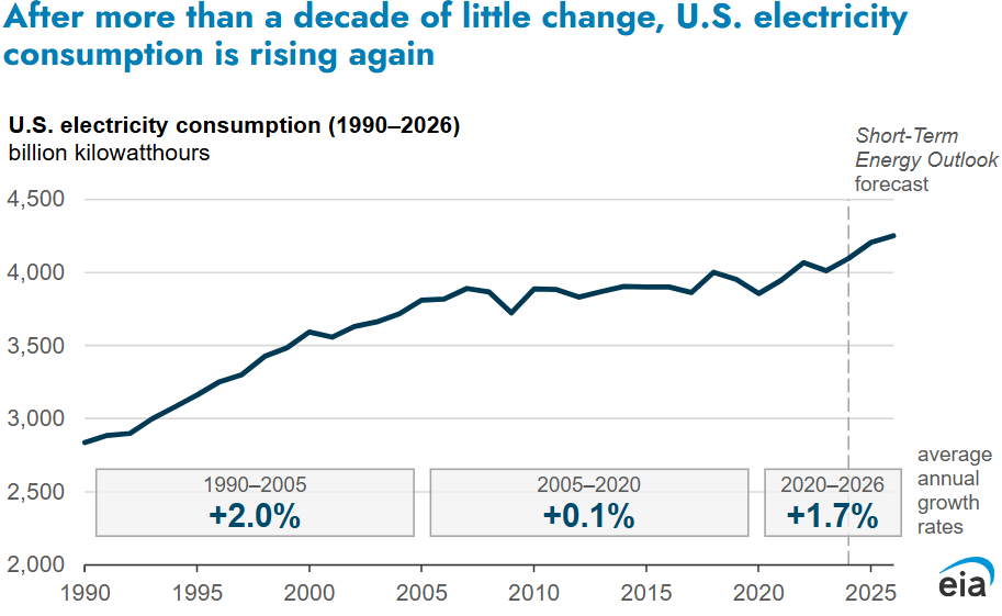
Source: EIA
In addition, there is a sizeable market for new, more efficient, cleaner, electricity-powered technologies. As such, we at Vivid believe it has become paramount for investors to be aware of the fundamental changes in science and economics that are enabling the energy transition.
Before we begin our investigation into all the exciting trends in electrification, we first must brush up on the fundamentals of electrical engineering and physics. Many students have lost their minds trying to understand the intricacies of electricity. Now it is our turn. To begin, let’s review the fundamental parameters we use to characterize electricity.
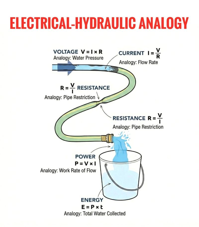
The easiest way to intuitively understand voltage, current, and resistance, in a circuit is via water flowing in a pipe.
Source: unspecified
In this analogy, the water pressure from a source is the voltage. This voltage is the “force” or “pressure”, often called the potential difference (in energy) that causes electrons to flow from one point to another. Voltage is a measure of difference in potential energy between two points along a circuit, where electricity wants to flow from a point of high voltage to low voltage. Voltage is measured in volts, V. Current, I (measured in amps), is then defined as the number of particles (water/electrons) flowing per second. The material’s opposition to this flow would then be the resistance, R, measured in ohms. Power, P, is defined as the rate of energy transfer and is a function of both voltage and current (), measured in watts, W (or J/s). Finally, total energy, E, is the integral of power with respect to time (watt-hours).
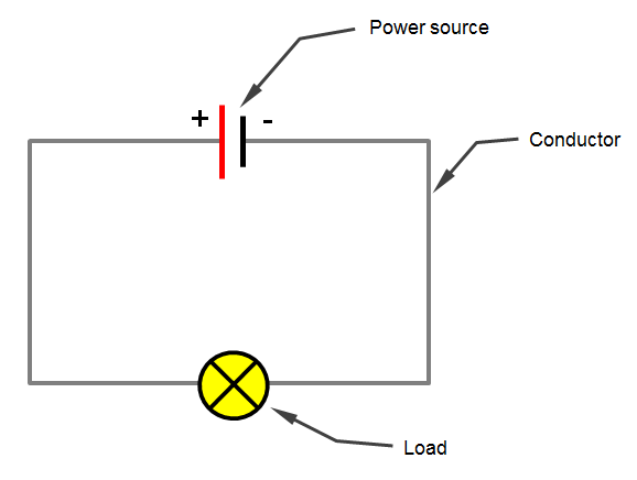
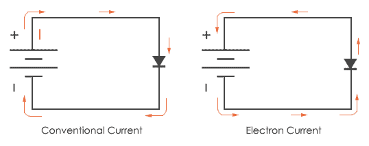
At its core, an electronic circuit is defined as a system of electronic components that work together to provide a path for electricity to flow. A simple circuit consists of 3 components: a power source, a load that consumes power, and the wiring to connect them. Electrons flow from the negative terminal (-) to the positive terminal (+). This is called electron flow. By convention, current tracks the opposite direction. Positive charges flow from the positive terminal (higher voltage, +) to the negative terminal (lower voltage, -). This is called conventional current. In the example below, the current flowing is determined by Ohm’s Law . The voltage “experienced” by the load is determined by the power source. The resistance is a physical property of the load.
Source: 12voltplanet.co.uk
Source: codery.com
Add a mechanical switch, and we can control whether or not the load receives power. In essence, we can control if a circuit is ON or OFF by physically connecting or disconnecting the wiring of the circuit. In later issues in this series, we’ll explore semiconductor switches that can turn a circuit path ON or OFF in response to voltage changes.
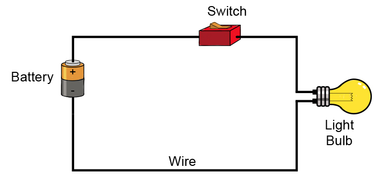
Source: mammothmemory.net
With that covered, we can then understand that in electrical circuits, voltage, current, and sometimes resistance, are not constant.
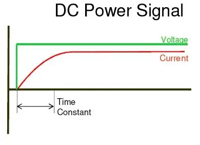
In the simplest case, let’s consider direct current, DC.
Source: gordonpowers.com.au
In this scenario, voltage is created near instantaneously via a switch as shown by the step function increase in voltage. This voltage causes a current to flow, but there is some start up lag. This lag is sometimes referred to as transience, and it depends on various factors relating to circuit design. For now, we’ll ignore transient properties and focus on the rest of the graph, which operates in what we call steady state. As we can see, current and voltage are the same sign and move together. This is the definition of direct current. Certain devices like solar panels and batteries innately output DC electricity, where electricity flows only in one direction. Meanwhile, certain devices, like computers are designed to specifically accept DC.
Next, let’s analyze alternating current, AC.
Source: gordonpowers.com.au
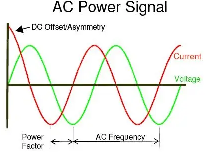
In this scenario, the voltage and current are oscillating between two peaks by crossing zero and reversing direction a certain number of times per second, called frequency, f, measured in hertz (Hz). The frequency of AC electricity in regional grids varies. The choice of transmitting electricity as AC instead of DC has an interesting history lesson that will be covered in a later report in this series. In North America, our grids operate at a frequency of 60 Hz (60 oscillations per second). Europe’s grids operate at 50 Hz, and most Asian grids also operate at 50 Hz. It should be noted that grid voltage also varies by region. This difference in the way regions transmit electricity is why you need a different charging block for your electronics when on vacation.
Sometimes, the voltage and current oscillate together in phase: when one is at 0, the other is too, and their curves overlap. If this is not true, then we say that the voltage and current are phase shifted. The amount of phase shift affects power factor, which is a ratio of useful power to the total (apparent) power in the system. If we ignore transient effects, and look at the repeating waveforms, we call this periodic steady state. Almost any turbine-based energy source will output AC. Meanwhile, devices such as motors, heaters, and lighting are designed to use AC. Engineers must design electronic circuits with both transient and periodic steady state effects in mind to ensure reliability and robustness for near-continuous operation.
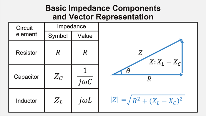
In AC operation modes, the frequency of current reversals directly impacts the AC equivalent of resistance, often called reactance, X. Reactive loads can be categorized as inductive or capacitive, which will be summarized in the following section. Inductive components interact with magnetic fields, while capacitive components interact with electric fields. Reactance is the imaginary (in the math sense) component of impedance, Z. Impedance is the vector sum of resistance (R) with reactance (X). The concept is summarized by a triangle diagram, shown below.
Source: Rohm
Using this information, we can then define reactive power, Q (measured in volt-amps reactive, VAR) in an AC circuit as the portion of electrical power being “used” by components with reactance. Real power, P (measured in watts, W), then refers to the portion of electrical power being consumed by components with resistance. The total power that needs to be supplied to the circuit is now defined as apparent power, S (measured in volt-amps, VA). The ratio of real power to apparent power is known as the power factor. In general, electrical engineers design AC circuits to operate close to a power factor of 1 by balancing capacitor and inductor values. In practice, connecting circuits together with many components and loads will often introduce unintentional capacitor or inductor-like effects, but we will not cover that here. Put simply, in AC operation modes, there must be a supply of reactive power and real power.
In DC, frequency is 0, and therefore there are no capacitive or inductive effects. In an ideal DC-only circuit, only real power exists.
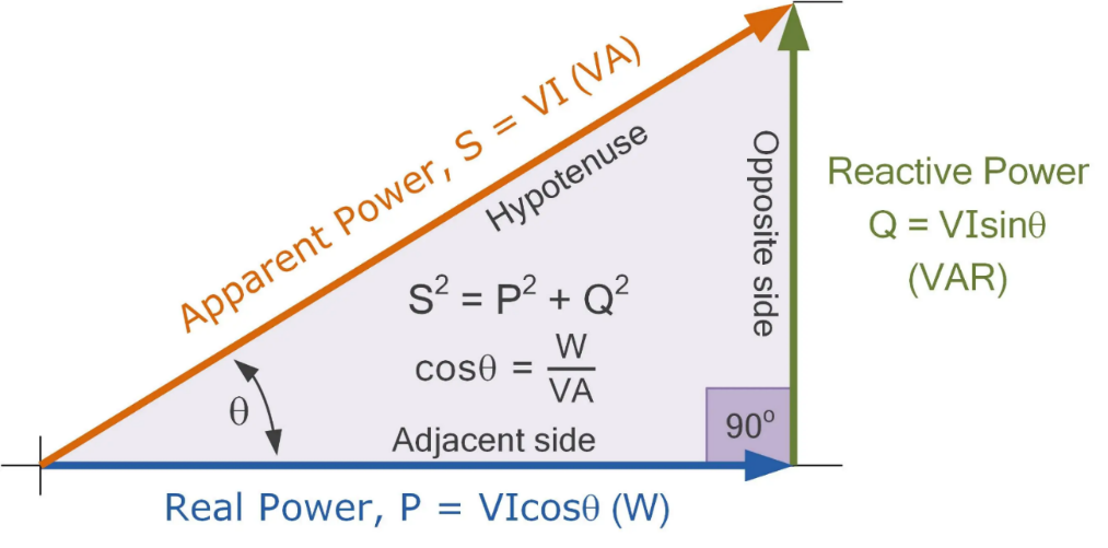
Source: electronics-tutorials.ws
A summary table below describes the fundamental electrical components present in almost any circuit. From these basic components, we can design circuits with a large variety of intended input and output characteristics. It is not necessary to know how each component specifically works, but note that each has its role in modern electronics and is considered an indispensable tool in an electrical engineer’s toolbox.


When designing circuits, there is a large array of factors that engineers take into consideration to ensure proper functionality, reliability, and longevity of the circuit. Listed here are three important factors that can make or break an otherwise well performing device.
Heat is a major consideration when designing any electrical system. This is because current (electrons) travelling in a conductive material will generate heat, as described by Joule’s Law:

In general, energy in a circuit can be accounted for in 3 categories: real power, reactive power, and heat losses. Real power is electrical energy that we associate with a useful outcome. This includes applications such as lighting, audio, or movement. Meanwhile, reactive power is energy that is not “consumed” but rather is inaccessible to our circuit applications because it is “used” to maintain magnetic fields in inductors and electric fields in capacitors. Finally, assuming the goal is not to make a heater, heat generation is considered an energy loss. In the context of efficiency, higher heat means lower efficiency. Standard power supply modules on the market using silicon-based technology usually have power efficiencies around 80% – 92%. This means 8% – 20% of electrical energy inputted into the power supply is wasted as heat before it even reaches the end use application.
It should also be noted that many I-V (current-voltage) relationships change with temperature. Therefore, it is necessary to specify an operating temperature range, and design the circuit with a certain cooling rate in mind to maintain that operating range.
EMI is major consideration when putting together components, or integrated circuits that depend on predictable magnetic forces. Because inductors emit magnetic fields into free space during their function, other inductors can react to these magnetic fields, leading to unintended energy transfer between different regions of a singular circuit, or with other magnetically sensitive components (like an electric motor). Therefore, shielding techniques are often used to isolate magnetic fields within the inductor. This can be done using specialized insulating materials, or by physically blocking the magnetic signal using a conductive metal.
Scientists ask “is it possible?”, while engineers follow up with “yes, but under what conditions, and for how long?”. Unsurprisingly, having robust equipment able to withstand brief periods of extreme operating conditions makes a product much better than one that breaks after one freak event. On top of this, every day reliability is also a consideration. Specific metrics to evaluate robustness and reliability are usually included within a product’s datasheet. With that said, many of these considerations are covered under specific certifications by various regional and international organizations such as the Institute of Electrical and Electronics Engineers (IEEE), Underwriters Laboratories (UL), International Organization for Standardization (ISO), etc.
If you’ve made it to the end of this report and read the entire thing, we congratulate you! In theory, you now have a better understanding of electrical engineering than most other investors. From here, it will be much easier to understand the topics to come in our later issues of this series. In our next issue of Science of Electrification for Investors, we will cover a hot topic in artificial intelligence that may have been forgotten too soon: The 800 Volt Transition.
Get the latest market insights and
research delivered directly to your inbox.
Intelligent exposure to the global energy transition.